

Outcome
Recognise each part of the installed system and understand its routine purpose.
Applies to
This guide covers the customer-facing parts used during normal measurement sessions. Your installation may contain a different number or arrangement of force plates.
Before you begin
- Use the component labels and connection diagram supplied for your installation.
- Do not open any enclosure or connect an unassigned port.
Steps
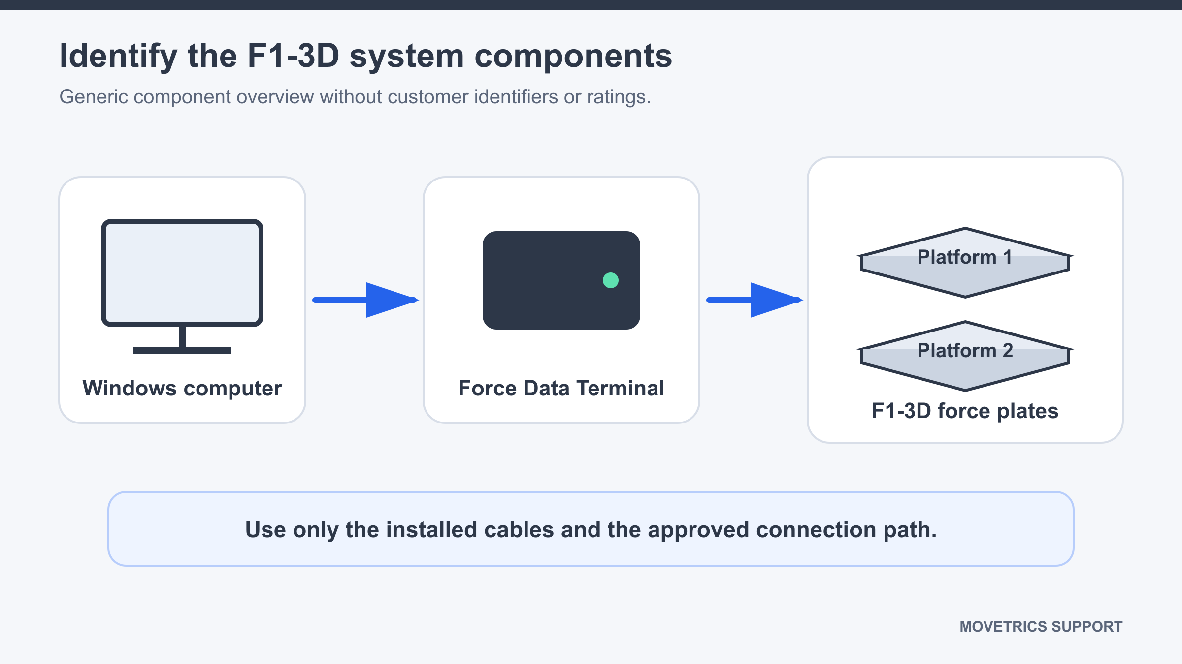
- Find the supplied Windows computer. It runs Movetrics Studio and holds the local project, Subject, and examination workflow.
- Find the Force Data Terminal. It forms the installed connection between the computer and the F1-3D force plates.
- Identify each F1-3D force plate by its visible plate label and marked orientation. Movetrics Studio refers to plates as Platform 1, Platform 2, and further platform numbers where applicable.
- Identify the supplied computer connection and the installed plate-link cables. Each cable should follow the connection diagram without tension or sharp bends.
- Identify the approved measurement surface and any customer-specific positioning marks.
- Check that all components belong to the installed system and that no temporary or unknown cable has been added.
You should now see
The computer, Force Data Terminal, force plates, and supplied cables can each be matched to the installed connection diagram.
Stop or repeat when
- A component or cable cannot be identified.
- A label is missing, a connector is damaged, or the physical system differs from the approved diagram.
If it does not work
Do not guess which port or cable to use. Photograph the overall setup without including personal information, record the unidentified item, and keep the system powered off until the connection is confirmed.